peet.za.net
ctrl-ocp-1 (Controller Office Cabinet Power 1)
Initial thoughts
This is not a pretty device. I did not have a proper enclosure and had to cannibalise a DC-DC converter - which is really small.
There is no disconnect should the battery run low. This is an issue as the battery is very expensive.
Everything is crammed inside, there's really not a lot of space.
Given my tremors and twitches the square hole for the voltage display isn't really square at all.
Measurements
Real-time:
- (INA219) 5V output (total on rear ports, excludes device itself) - Voltage, Current, Power
- (INA219) 12V output on each DC jack - Voltage, Current, Power
Hardware
The chassis is a non-functioning DC-DC "mini-UPS" powerbank that was stripped.
It has an ESP8266EX microcontroller with a Tensilica L106 32-bit cpu running at 160Mhz, with 4MB of flash memory.
Generic 3A variable DC-DC converter (used to convert 12V input to 5V output).
Front
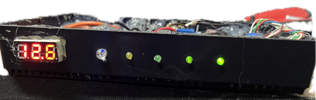
The 3-digit 7-segment display shows the voltage of the input line.
The RGB LED that indicates the device status. It is simply used as:
- Blue (blinking): Attempting to connect to WiFi network.
- Green: All is good.
- Red: An error has occured (e.g could not find INA219 sensor, etc).
Yellow LED: Something is using power via the 5V connector.
3 Green LEDs: One for each 12V DC female jack, also indicates if something using power via that connector.
Back
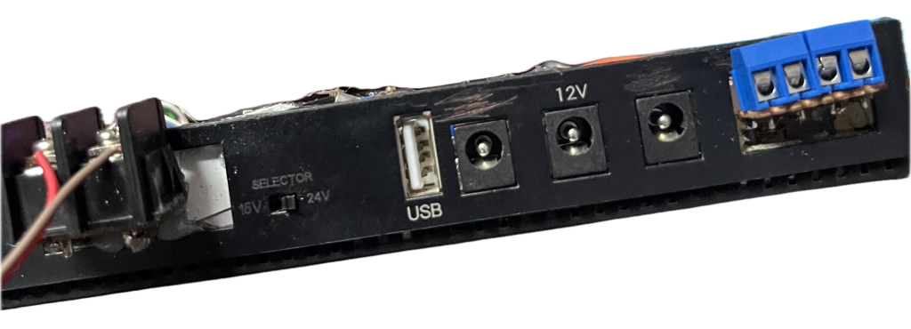
Input: 12V screw terminal connector.
The selector switch and the USB port is not in use.
Output: 3 (salvaged) female DC jacks in the rear, each running through an INA219 Voltage/Current/Power sensor, all of which are connected to the ESP8266 via a single I2C bus.
Output: dual 5V screw terminal connectors, also on an INA219.
Inside
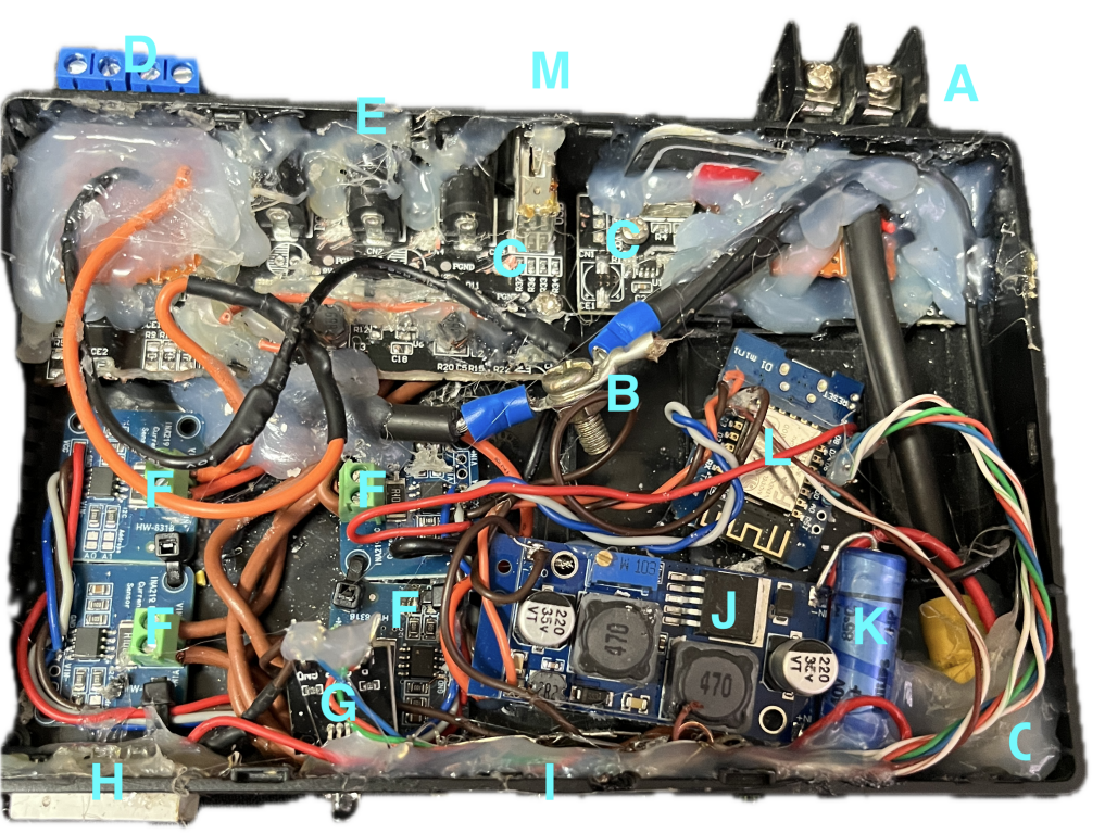
As you can see everything is glued together very well. This is purely to secure the boards and wires, to make sure it doesn't move and cause a short.
- A. 12V battery connection.
- B. GND junction.
- C. +12V junction.
- D. Dual 2-pin screw connectors for 5V output.
- E. 12V female jacks.
- F. INA219 sensors - one for each 12V jack, and one for 5V output.
- G. RGB LED module.
- H. 3-digit 7-segment voltage display.
- I. LEDs
- J. Adjustable DC-DC converter supplying 5.1V to the ESP and USB.
- K. 470uF Capacitor on 5V output.
- L. ESP board.
- M. (Not shown) USB cable hanging out the back.
- N. Original circuit board that remains due to connectors.
Completed project
Initial installation location in the 9U cabinet.
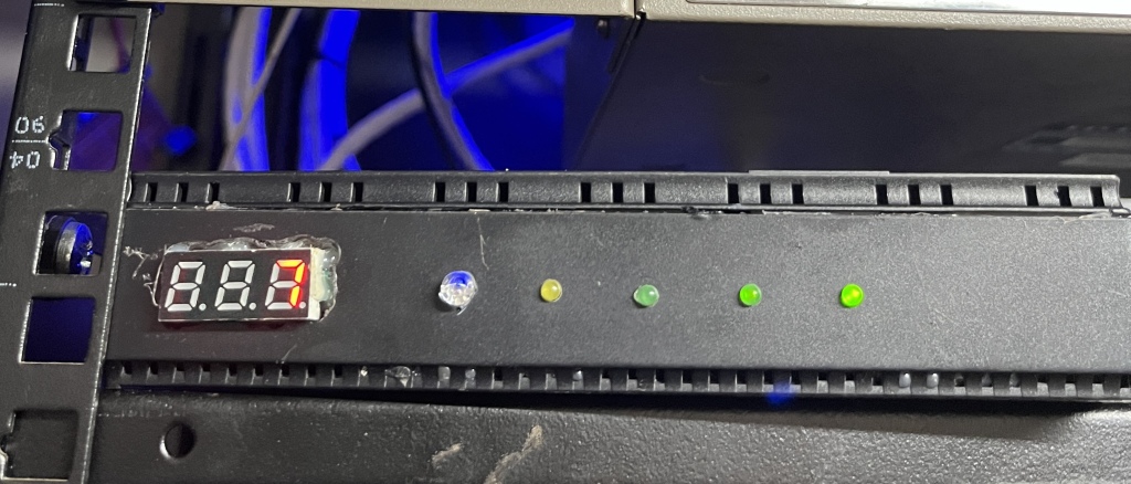
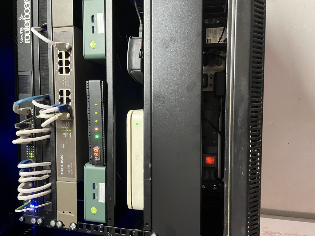
Permanent residence in cabinet, between the two nuc boxes. The TP-Link switch above the controller is the one that stopped working, and now houses ctrl-hcp-1, the home 12V distribution box.
Prophet functionality
The ESP controller has an HTTP server, providing the following information on request in real-time: WiFi RSSI, Free Heap memory, all 4 INA219 sensors Voltage, Current and Power.
The fullowing information is pushed to Prophet:
- Any LED state change.
- If the voltage drop on one of the 12V DC jacks is less than the previous reading. (debugging purposes)
- If the current usage on any one of the 12V DC jacks or the 5V supply becomes < 200mA.
Standard for all controllers, $IP/reboot reboots the controller, $IP/disable disables the controller by going into an infinite loop.
Thoughts
- There is no protection, mainly because the battery input goes through a dual-pole DC breaker [Battery], a fuse, another dual-pole DC breaker [Load], and another fuse, and another single-pole DC breaker.
- It's not too ugly, but the 7-segment voltage display on the front should've been mounted better.
- The 12V input cable (it's 4mm wire) came loose more than once while I was shifting things around in the cabinet. I ended up using heat-shrink over the wire and the crimped connectors, and it seems to work very well.
- All the device does is distributing power and monitoring the usage. Even if the controller is disabled, the power supply will still be present. Even if the ESP stops working completely, it will still perform it's primary function.
- The ESP OTA updates stopped working, so I had to open up the device again to plug in a USB cable. At the time it seemed like a good idea, so I added a USB cable to the device, hanging out the back, lying on the cabinet's bottom. This allows me to pug in a USB extension cable and either program it via serial port, or receive serial output from the ESP.
Concerns, missing things, etc
The device has no way to shutdown the load if/when the battery gets low. It needs relays for the 12V and 5V output (ESP should still be powered). ESP would then set all LED states to error, and go into deep sleep. Possibly wake up every couple of minutes (without wifi) to check voltage.
Ideally this device should act as a UPS and notify the nucs and router when it's about to disconnect the load, to allow for proper shutdown. Either via USB or probably more easier nut.
There is no protection, power switch or reset switch. It should have at least a fuse and power switch in front, and possibly a reset switch at the back. The DC DB board does provide the required protection, but it can't hurt having more
The case is very small, more space would be useful.
A rack-mount case would be ideal.